Dear friends,
Old friend of mineMorda (Airsoft Team Unity, Šiauliai) is known for its technical expertise and diligence – he is the very first who built minigun in Lithuania (and most likely in the Baltic States). Now, he is sharing a very good and well prepared PTT improving instruction with readers. I am pleased to announce it to you. Thanks Morda and good work for you all!
Hi there,
Many of us who use PTT (push to talk) will face with bad contact problem. This is a very common problem. The biggest problem is that metal contacts of PTT is angled and military standard plug bends it in time. Another problem is inside the button, it does not seem very reliable. After I bought this PPT I immediately encountered with a problem that PTT did not respond. Dismantling revealed bad contact plate position. After inserting the plate into place button started working, but it was decided to change it to something more reliable.
I decided that it would be useful to write a brief description of Peltor PTT replica modification and improvement. Maybe someone will find this instruction useful.
From the beginning …
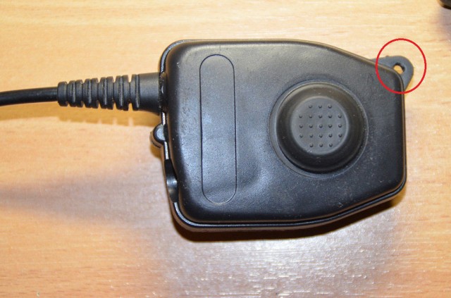
Take off the top shell piece, it is removed by undoing the screw on the “tongue” (marked in 1 pic.).
7 unscrewed screws remove the back cover of the PTT (2 pic.).. Some manufacturers pour hot glue on the corner (1 marks the place on picture), remove it.
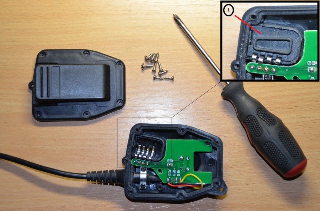
Remove the part 1 (2 pic.).
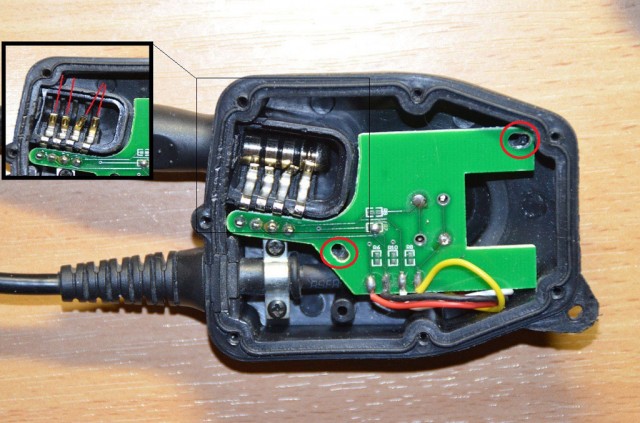
As you can see (3 pic.) one of the contacts is bent. Remove the 2 screws (marked) and remove the motherboard.
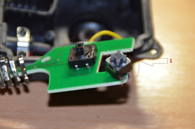
Re-solder buttons (4 pic.).. No. 1 – old button, no. 2 – new.
Remove the two screws holding the cable to the PTT housing and remove it (5 pic.).
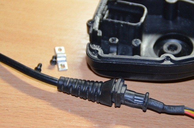
Next step – cut / drill / remove the selected location of PTT housing (6 pic.) And increase the selected hole (7 pic.). Enough to fit the microphone connector jack (the – socket).
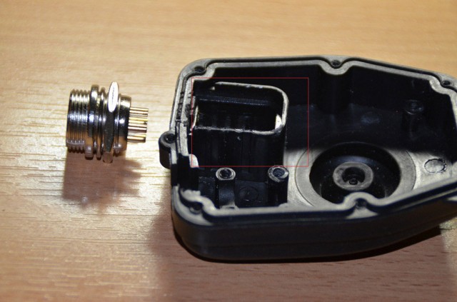
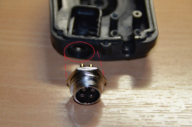
After several minutes of cutting and drilling the result we obtain is as follows (see 8 and 9 pic.).
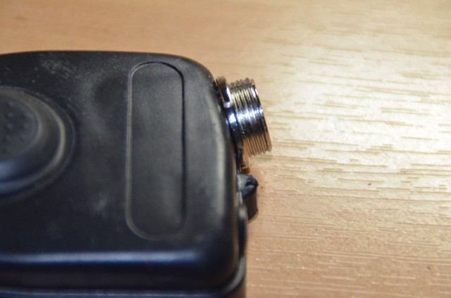

Installation work is complete, now we take a soldering iron and move on to more thorough part.
Solder four wires to the microphone jack contacts (10 pic.). Used 4-pin socket, because the original plug has 4 contact points. You can also use more contact slots, but 4 pin is enough.
Solder four wires from the socket in the place of the motherboard contacts (10 pic.).
The small print is numbering the contacts on the microphone jack and plug, that would be more convenient to trace the ends of wires. My soldering sequence shown in 10 and 11 pic.
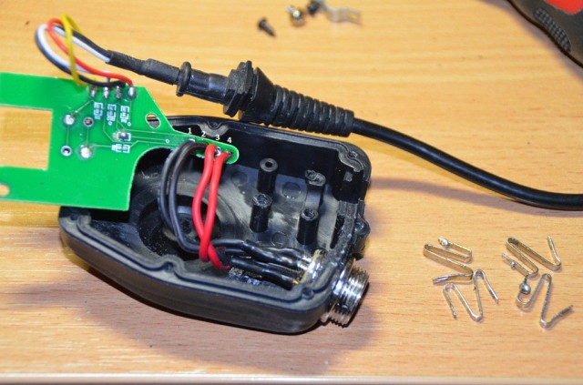
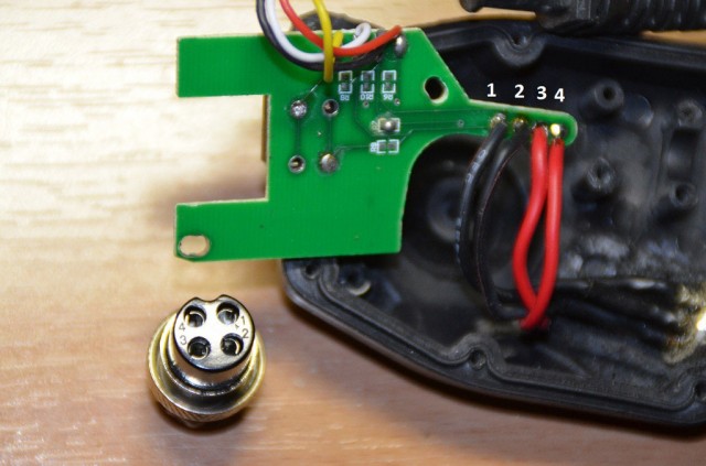
After soldering work assemble the PTT (12 pic.).
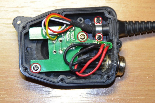
Tighten the back cap of PTT (13 and 14 pic.).
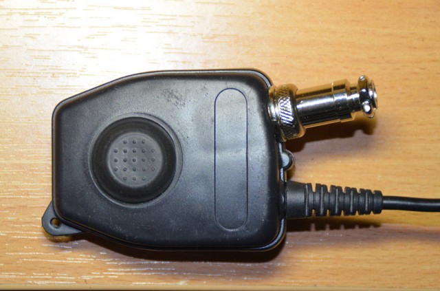
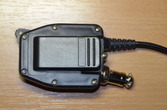
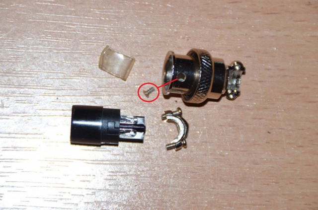
At this stage, most PTT should be finished. Now move on to the military standard plug. Dismantle the microphone connectors plug. Unscrew the small screw located on the side (see 15 pic.).
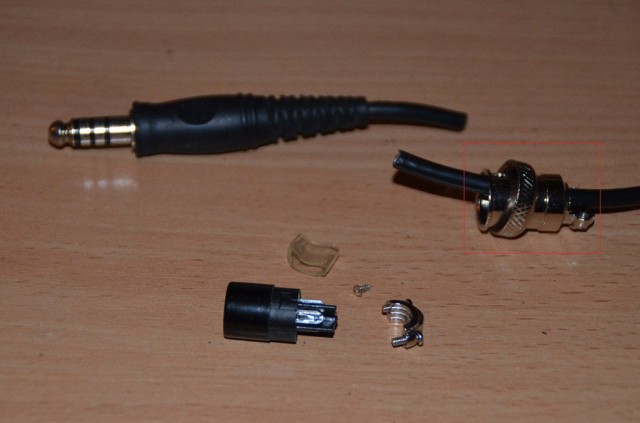
Cut the wire of the headphones military standard plug leaving 1-2 cm cable to the plug (16 pic.). Tip – after cuting the wire put the plug of the microphone on the headphone cord. Do not mix in which direction it should face :) Right direction on 16 pic.
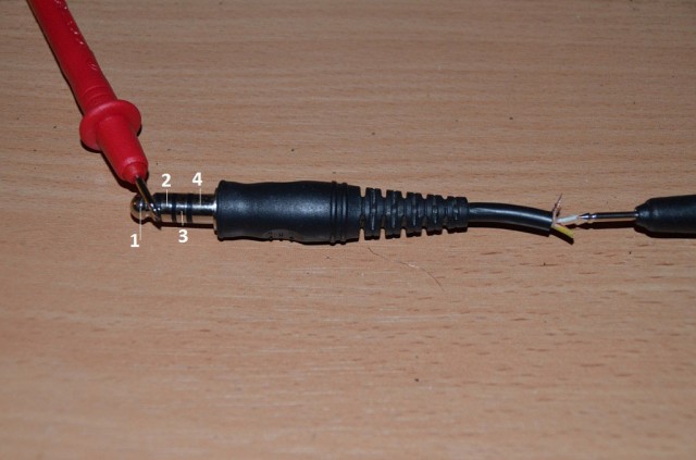
Move on to the connector pin solding. Inspect which part of the plug corresponds to a specific color wire on the end of the cord with a multimeter (17 pic.). Please note that the figures corresponds to the number on the plug located on the main board (11 pic.). Do not mix the sequence.
Once a suitable wire color and numbering is matched – solder it (18 pic). Solder the remaining wires (19 pic.).
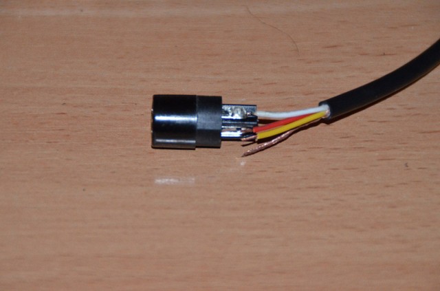
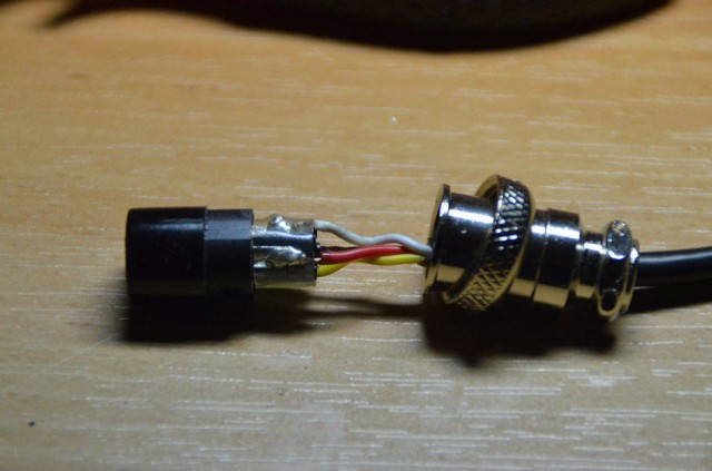
Connect the metal and plastic parts of the plug with with a screw (20 pic.). The plug is done.
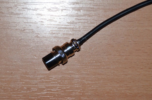
You can connect the plug to socket and check if everything is working.
Good luck improving


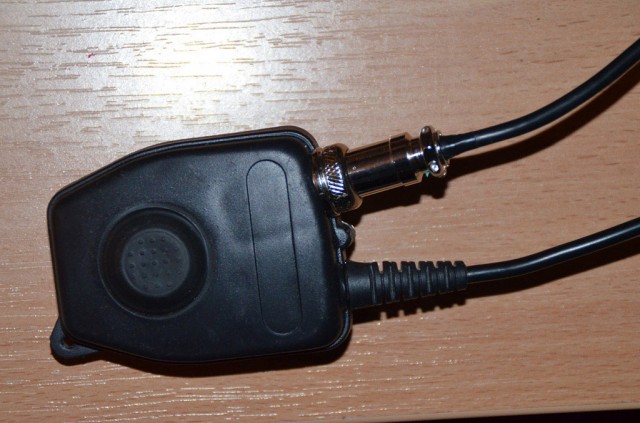
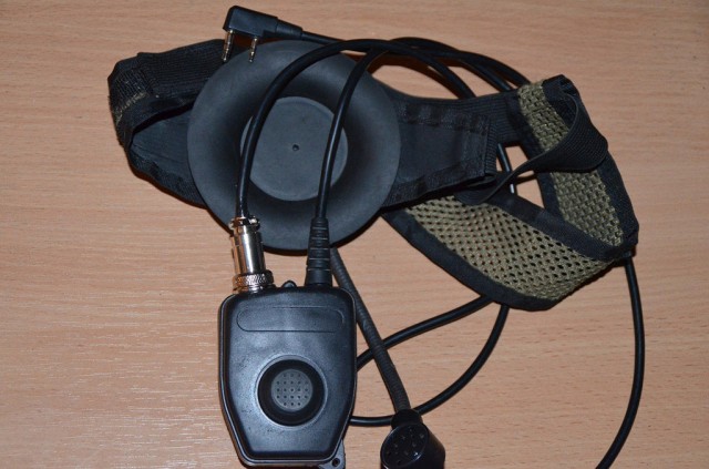
Ant jungties blizgančios dalies galima užmauti termokembriko.
Nebus demaskuojančio blizgesio ir atodys labiau :) military.